
CEMS Uptime and Compliance
Posted on July 11, 2018
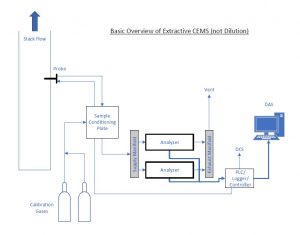
There are many different manufacturers for both CEMS and COMS, as well as a wide variety of system configurations. The system configurations for CEMS are typically dictated by the emission requirements and facility process environment, e.g. dirty, wet, and/or flammable sample streams, just to name a few. The most basic CEMS configuration is likely to be an extractive system that is not using dilution to transport the sample to be monitored. These systems are usually selected in locations that are “clean” and without a harsh sampling environment. Extractive systems typically consist of a probe that is mounted in the sampling location (e.g. flu stack), a sample umbilical, sample conditioning system, pump, analyzers, PLC, and data acquisition system (DAS). The probe will likely have some sort of filter to keep unwanted material from traveling into the sampling system. The probe will also usually be heated to maintain the integrity of the sample being collected. The sample umbilical can vary, and some typical options can consist of spare sample tubing, calibration gas tubing to deliver calibration gases to the probe, air line for probe blow back, power supply for probe components, and are also usually heated to a specified temperature consistent with the geographic location of the facility and sample gas composition being transferred. Sample travels through this umbilical to a sample conditioning system/plate. These systems remove moisture and “dry” the sample gas, as most emission requirements specify this as a requirement. This step also helps protect the components within the analyzers that are downstream of the sample conditioning system. There will also need to be a pump or venturi air mover that will create a vacuum to pull the sample from the probe location and deliver it to the location of the analyzers. In addition, the analyzers may have internal pumps while others may have external pumps which are located on the exhaust end of the analyzer. These pumps are specific to each analyzer and are designed to pull what each analyzer requires for flow to achieve proper analysis. The excess sample gas will be vented so that the analyzers are not pressurized. Subjecting the analyzers to pressure can lead to inaccuracies in the analysis. Once the analyzers determine the sample concentration, that information is transferred from the analyzer to a PLC, or datalogger. The PLC/logger can also receive inputs from the sample conditioning plate such as flows, pressures, moisture, etc. Generally, the information from the PLC/logger is then fed to a DAS and/or to a DCS for operations to view. It is best to be using a DAS for your reporting needs and data storage since those systems are designed specifically for CEMS data calculations, storage, and reporting. What was just briefly described here is a very general and basic overview of what can comprise an extractive system; however, as mentioned previously, there is a wide variety of configurations. The following figure gives a general visual representation of what is being described.
Techniques to Maintain Uptime
One of the biggest factors for maintaining uptime, as we discussed in our previous article, is preventative maintenance.
- Conduct preventative maintenance during a process outage since it will not count towards your CEMS downtime. These opportunities are few but nonetheless great times for CEMS maintenance.
- Develop a schedule for typical preventative maintenance items, such as pump rebuilds, filter replacement, O-ring replacement, orifice cleaning, etc. Having a monthly, quarterly, semi-annual, and annual plan in place for maintenance items will keep your system running smoothly.
- Spread maintenance tasks amongst multiple months to reduce large quantities of downtime whenever possible.
- Review calibration checks as soon as possible after they occur to ensure any problems indicated by the calibration check are addressed immediately by troubleshooting, repairing, and recalibrating the CEMS. Unnecessary downtime could be accumulated if the CEMS fails and is not identified immediately.
- Train the technicians who maintain the CEMS to understand the importance of the CEMS and the repercussions to the facility if they are not maintained correctly. Operators who periodically check emissions reported by the CEMS throughout their shift should also be trained to understand the level of priority the CEMS require if they suspect the reported values are not correct.
Often Overlooked Compliance Issues
Data is the end result and ultimately the purpose for a CEMS and requires vigilant management.
- Review data daily for any suspect data. If there is data that appears to be suspect, the CEMS should be evaluated to determine if it is valid.
- Verify that the data was flagged back to the previous good calibration check when a calibration failure does occur.
- Check data to ensure the correct minutes of data have been excluded when preventative maintenance is performed. This will confirm those maintenance timeframes are not included in the averages.
In our next article, we will touch on COMS overview, maintaining uptime, and overlooked compliance issues as well. In the meantime, if you have questions or concerns about your CEMS and COMS, please contact Environmental 360 today to see what we can do for your system’s uptime.